\(
\DeclareMathOperator*{\oiint}{{\normalsize{\subset\!\supset}}
\llap{\iint}} \)The 2-Sphere
as the Configuration Space of a Mechanism
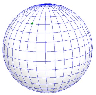
Consider a mechanism with a 2-sphere as its configuration space
(c-space).
A CAD model of a spherical pendulum
2-Sphere
Consider a massless rigid rod with a bob with mass \(m\) at one end and
a ball-and-socket joint attached to ground at the other end. This has a
standard 2-sphere as its configuration space (c-space) (technically, it
only has a compact subset with boundary as the c-space; in this case, I
refer to the whole 2-sphere as the natural completion of the c-space).
The Riemannian
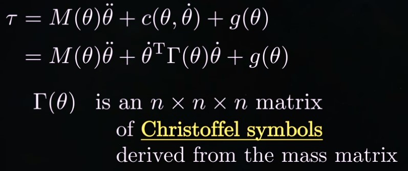
metric (r-metric) \(g(\theta, \phi)\) (written as \(M(\theta)\)
in the
following graphic from https://youtu.be/BjD-pL819LA?si=q8_It-jJFEq0AmEu&t=212;
\(g(\theta)\) in the following graphic is the gravity term) may be read
off the equation of motion (EoM):
The Riemannian metric in a coordinate patch using \(\theta\) and \(\phi\) for this mechanism is given by
Note that the entries in the Riemannian metric
have dimensions of \(\left[\text{Length}^2 \cdot
\text{Mass}\right]\). (It should be noted that there are
dimensions/units used for the
describing the robot arm and hence, perhaps bizarrely, for describing
the
Riemannian metric. Points in the
manifold and tangent vectors to the manifold are part of the intrinsic
topology of the underlying smooth manifold of the c-space and have only
dimensions of [Angular Measure], while inner products/norms of tangent
vectors and
lengths of curves/distances between points in the manifold depend on
Riemannian metric, which is extrinsic to the topology of the underlying
manifold; inner products of tangent vectors have dimensions of
\(\displaystyle\left[\text{Angular Measure}^2\cdot\text{Length}^2 \cdot
\text{Mass}\right]\) while norms of tangent vectors and lengths of
curves/distances between points have units of
\(\displaystyle\left[\text{Angular Measure}\cdot\text{Length} \cdot
\text{Mass}^{\frac{1}{2}}\right]\). This kind of r-metric is known as
the "mass matrix'" and morally has dimensions of mass. The way that
things work out here, there are \(I_{zz}\) terms, and we can't just
move the lengths to the \(\theta\) factors. But, morally, the mass
matrix has dimensions of mass.)